Support
How to adjust the slow start.
How to install the air pack 1 assembly.
How to install the air pack 2 assembly.
How to install the air pack 3 assembly.
How to install an NDT kit.
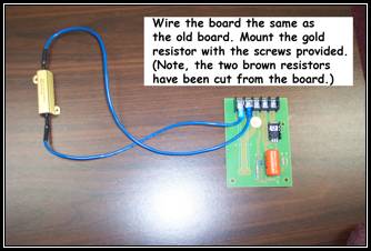
How to install the current transformer kit.
My machine is missing flaws, what is wrong?
What kind of flaws can the NDT detect?
I have an NDT that did not arc to an obvious flaw why not?
My machine will not arc to any flaw, why?
The NDT arced but did not stop automatically while in the start (automatic) mode, why?
My test tire did not trigger a flaw condition, why?
How the NDT can save your money.
How does the NDT work?
Who uses electronic tire inspection, NDTs?
When I press the start button, nothing happens, why?
My motor won't turn, why?
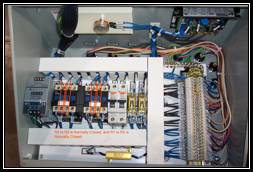
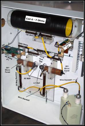
What are the parts in the High-Voltage Cabinet called?
The swing arm won't swing in, out, up, or down, why?
The 2-amp circuit breaker disengaged, why?
What maintenance should I do to the NDT?
NDT maintenance schedule.
How do I change the sensitivity of the detector circuit board – old detector circuit?
How do I change the sensitivity of the detector circuit board – new detector circuit?
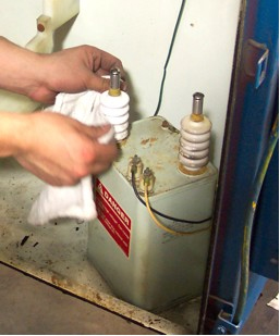
1. 50KV power supply When this unit fails it will leak a clear mineral oil stored inside, or cracking on the porcelain post will be visible, or a bulge in the side of the power supply will develop. Detection of a failed power supply will be noted when no high voltage is created. Usually, if there is no high voltage, there is some other issue causing the problem not the 50KV power supply. Check the 2-amp circuit breaker, capacitors, 1 Meg resistor, 20 Meg resistor, and 75-ohm resistors before replacing the power supply.
The porcelain posts of the power supply are very susceptible to surfacing tracking of electricity when they become dirty. Clean the porcelain posts with a clean dry rag (do not use solvents) regularly. Occasionally, if the porcelain posts are dirty, the operator may complain of a loud band. Usually, cleaning the porcelain posts will fix the complaint of a loud bang; however, the problem could be from an open 1 Meg or 20 Meg resistors.
Clean the entire high-voltage cabinet once a year minimally to ensure these issues do not develop into larger problems.
How to Clean the 50 KV Power Supply
 Warning, always discharge voltages in the high-voltage cabinet before contact with the electronics. Although, the cabinet is designed to discharge the voltage, it is possible that voltages remain stored indefinitely. Ensure that all ground wires are in good condition during scheduled maintenance.
2. 1 Meg and 20 Meg resistors. Both resistors are susceptible to damage if oil deposits from handling remain on the resistor. Therefore, after handling these resistors wipe the resistors with a clean dry rag (do not use a solvent) to remove oil deposits left from handling.
When standing in front of the high voltage cabinet, the 20 Meg is on the left, and the 1 Meg is mounted on the right. If there is no high voltage, measuring these two resistors is the second step in diagnosis of the problem. The first is to check the 2-amp breaker. It is important that 1 Meg and 20 Meg resistors be cleaned periodically to remove buffer dust and other dust that settles in the high voltage cabinet. Dust and debris that collects on the resistors can cause the resistors to fail and the electricity to surface track over the resistor. When the electricity surface tracks, the critical frequency is compromised, and the detector will not function optimally.
Clean the entire high voltage cabinet once a year, to ensure surface tracking of the electricity issues do not develop into larger problems. (When measuring the 1 Meg and 20 Meg resistors, ensure that the probe does not contact any part of the machine's structure. If the output wire, Key Chains, or Sidewall wires contact the structure of the NDT, a sneak path can cause an ohm measurement to be erroneous.)
Both the 1 Meg and 20 Meg resistors are mounted by with resistor bands and plastic standoffs. On older NDT machines, the resistor bands can fatigue and break. Additionally, the plastic standoffs become brittle and can break causing the resistors to hang by the wiring. This situation is dangerous and should be fixed immediately. Replacement of the entire resistor assembly is optimal. If only the bands and standoffs are replaced, ensure that the resistor functions properly by measuring each resistor with a multimeter.
Warning, always discharge voltages in the high-voltage cabinet before contact with the electronics. Although, the cabinet is designed to discharge the voltage, it is possible that voltages remain stored indefinitely. Ensure that all ground wires are in good condition during scheduled maintenance.
3. Plexiglas plastic and resistor mounting.. The plastic is shaped and spaced to prevent surface tracking of the electricity. Occasionally, a resistor (1 Meg, 20 Meg, 5K Ohm, 150 Ohm, or 75 Ohm) will fail or other containments will collect on the Plexiglas or resistor mounting, which will cause surface tracking of the electricity. When this occurs, a carbon-mark may be seen on the Plexiglas or resistor mounting. If there are traces of carbon marks, which may look like melted or burnt spots, replace the plastic. If the plastic is not replaced, electricity will take the path of least resistance, and could surface track across the carbon mark even after the containments are cleaned or resistor is replaced. For example, if there is a burnt, carbon mark, or any damage to the Plexiglas or resistor mount replace those parts as well as remedy the reason for the occurrence of the mark. If only the cause of the carbon mark is replaced and not the plastic that retains the electrical carbon mark the problem will reoccur.
Warning, discharge voltages in the high-voltage cabinet before contact with the electronics; although, the cabinet is designed to discharge voltage, it is possible that voltages remain stored indefinitely. Ensure that all ground wires are in good condition during scheduled maintenance.
4. Capacitors. The capacitors contain a clear mineral oil. Two capacitors are mounted is series with each other. When the capacitors are fully energized, a discharge from negative to positive occurs.
To verify the capacitor has failed check for leakage of the clear mineral oil, which is often difficult to see, or carbon markings or burning on the failed capacitor. To conclusively diagnosis a failed capacitor use a meter that is capable of checking capacitance.
Often when one of the capacitors fails the 2-amp circuit breaker, which protects the 50KV power supply will disengage. However, a disengaged 2-amp circuit breaker could be caused by a failed 1 Meg resistor, 20 Meg resistor, 50KV power supply, or even a bad 2-amp breaker.
Warning, discharge voltages in the high-voltage cabinet before contact with the electronic components; although, the cabinet is designed to discharge voltage, it is possible that voltages remain stored indefinitely. Ensure that all ground wires are in good condition during scheduled maintenance.
5. Carbon Spheres. The carbon spheres thread onto the capacitors. When installing new carbon spheres use caution because the carbon material is much softer than the steel stud of the capacitor and the carbon spheres are susceptible to stripping of the treads if over tightened.
When standing if front of the high-voltage cabinet, the small carbon ball is on the left, and the large carbon sphere is mounted to the capacitor on the right.
The critical frequency is dependant on the gapping of the carbon spheres. The optimum gap is 11/16th inch. However, depending on atmospheric conditions this distance could vary, but is should be insignificant, so once every 6 months gap the carbon spheres to 11/16th inch. The reason for gapping the carbon spheres is that the carbon spheres wear due to heat. Because the spheres flatten, the spacing between the spheres widens causing the 11/16th inch gap to increase.
If a flat spot grows to ½ inch in diameter, replace both the small and large carbon ball. When the carbon spheres gap increases so does the energy, hence the ability to arc to a flaw. However, the popping rate slows, which will decrease the inspection area of the tire. Additionally, any gap that varies from the 11/16th inch will cause the critical frequency to change and cause the detector to function ineffectively.
Warning, discharge voltages in the high-voltage cabinet before contact with the electronics; although, the cabinet is designed to discharge voltage, it is possible that voltages remain stored indefinitely. Ensure that all ground wires are in good condition during scheduled maintenance.
6. 75-Ohm resistors There are two 75-ohm resistors in the circuit used to create the voltage necessary to inspect steel belted tires.
If there is no high voltage when the Steel / Fabric selector is set to the steel position, measure these resistors to ensure that the circuit is good.
A by-product of high voltage is ozone. Occasionally, ozone will react with other chemicals to form new compounds. For example, compounds may form as liquids, or as corrosion, and will be visually apparent on many parts in the high voltage cabinet.
Cleans these resistors with a clean dry rag (do not use a solvent) once a year.
The two 75-ohm resistors are part of the circuit for fabric. The fabric circuit requires that both high voltage relays (relay #1 and relay #2) be in the open state. When high voltage relay #1 (the relay mounted to the left wall of the high voltage cabinet) is open, electricity is routed through the two 75-ohm resistors, through two 5-k ohm resistors, and then through two capacitors to complete the circuit.
When measuring resistors, ensure that the probe does not contact any part of the machine's structure, if the output wire, Key Chains, or Sidewall wires contact the structure of the NDT, a sneak path can cause an ohm measurement to be erroneous.
Warning, always discharge voltages in the high-voltage cabinet before contact with the electronics; although, the cabinet is designed to discharge the voltage, it is possible that voltages remain stored indefinitely. Ensure that all ground wires are in good condition during scheduled maintenance.
7. 5 K Ohm resistors. These resistors are part of the circuit used to create the voltage necessary to inspect fabric belted tires.
If there is no high voltage when the Steel / Fabric selector is set to the Fabric position, measure the 5-K resistors to ensure that the circuit is good.
A by-product of high voltage is ozone. Occasionally, ozone will react with other chemicals to form new compounds. For example, compounds may form as liquids, or as corrosion and will be visually apparent on many of the parts in the high voltage cabinet.
Clean the 5 K ohm resistors with a clean dry rag (do not use a solvent) once a year.
The fabric circuit requires that both the high voltage relays (relay #1 and relay #2) be in the open state. When high voltage relay #1 (the relay mounted to the left wall of the high voltage cabinet) is open electricity is routed through two 75 ohm resistors, through two 5 k ohm resistors, and then through two capacitors to complete the circuit.
When measuring these resistors, ensure that the probe does not contact any part of the machine's structure, if the output wire, Key Chains, or Sidewall wires contact the structure of the NDT, a sneak path can cause an ohm measurement to be erroneous.
Warning, always discharge voltages in the high-voltage cabinet before contact with the electronics. Although, the cabinet is designed to discharge voltage, it is possible that voltages remain stored indefinitely. Ensure that all ground wires are in good condition during scheduled maintenance.
8. 150 Ohm resistors. The 150-ohm resistors are output resistors. The resistor on the right, when standing in front of the high voltage cabinet, is used in the steel circuit only. Both resistors become a series of resistors, and are used for the fabric voltage circuit.
When the Steel / Fabric selector is positioned for steel voltage, and a flaw occurs in the tire, electricity is routed from the output of the capacitor, through high-voltage relay #2, through only one 150-ohm resistor; the 150 ohm resistor on the right; then out to the flaw. When the Steel / Fabric selector is positioned for fabric voltage, and a flaw occurs in the tire, electricity flows from the output of the capacitor, through the high-voltage coil, then through both 150-ohm resistors and out to the flaw.
A by-product of high voltage is ozone. Occasionally, ozone will react with other chemicals to form new compounds. For example, compounds may form as liquids or corrosion and will be visually apparent on these resistors. Clean these resistors with a clean dry rag (do not use a solvent) once a year.
When measuring these resistors, ensure that the probe does not contact any part of the machine's structure. If the output wire, Key Chains, or Sidewall wires contact the structure of the NDT, a sneak path can cause an ohm measurement to be erroneous.
Warning, discharge voltages in the high-voltage cabinet before contact with the electronics; although, the cabinet is designed to discharge the voltage, it is possible that voltages remain stored indefinitely. Ensure that all ground wires are in good condition during scheduled maintenance.
9. High Voltage Relay #1 and #2. These relays are used to route electricity based on the Steel / Fabric selector. When the selector is positioned for steel voltage, both relays are in the closed position and the coils of the relays are not energized. When the selector is positioned for fabric voltage, both relays are in the open position and the coils of the relays are energized.
A by-product of high voltage is ozone. Occasionally, ozone will react with other chemicals to form new compounds. Compounds may form as liquids or as solids such as corrosion and will be visually apparent on the moving bus bar and fixed position contacts of the relay. Use emery cloth or a fine-grit sand paper to remove corrosion from the moving bus bar, and fixed position contacts once a year. Additionally, the metal block that slides back and forth in the coil of the relay tends to rust. The relays should be cycled periodically reduce seizure due to rust. If there is a lot of rust, the relay can be disassembled and the metal block that slides back and forth in the coil can be buffed clean.
Warning, discharge voltages in the high-voltage cabinet before contact with the electronics; although, the cabinet is designed to discharge voltage, it is possible that voltages remain stored indefinitely. Ensure that all ground wires are in good condition during scheduled maintenance.
10. High-Voltage Coil. The 6 by 20 inch coil is used to increase the output voltage used for inspecting fabric tires. When measuring the coil it should read approximately 6-7 ohms.
Warning, discharge voltages in the high-voltage cabinet before contact with the electronics; although, the cabinet is designed to discharge the voltage, it is possible that voltages remain stored indefinitely. Ensure that all ground wires are in good condition during scheduled maintenance.
10.5 High-voltage wiring Wires in the high-voltage cabinet are routed specifically to prevent surface tracking of the high-voltage electricity, and to ensure proper function of the NDT. When replacing wires, it is critical that the replacement wires match exactly with the factory routing. Some wires use plastic standoffs to ensure that the wire does not contact metal. Additionally, some wires carry positive voltages, and some carry negative voltages. If the routing of the positive and negative wires is too close to each other, arcing will occur.
11. Main disconnect and uses. The main disconnect and fuses act as a safety checkpoint. When the high voltage cabinet door is open, the red handle can be used for lockout tag out procedures. The red handle connects to a 12 inch shaft, which is connected to the mechanism that when in the off position disconnects line voltages from the main electronics.
There are two 15 amp slow blow fuses used in the disconnect. Both the line and neutral are fused. The main disconnect should be inspected once a year for excessive corrosion and replaced at the discretion of the inspecting technician. Additionally, if the red handle is damaged it should be replaced especially if the handle is cracked or allows debris in the cabinet.
Warning, discharge voltages in the high-voltage cabinet before contact with the electronics; although, the cabinet is designed to discharge the voltage, it is possible that voltages remain stored indefinitely. Ensure that all ground wires are in good condition during scheduled maintenance.
12. Reset Relay This relay is used for safety. Three normally open contacts close when the operator presses the black reset button on the side of the high-voltage cabinet. If the NDT machine does not reset the three contacts should be checked for continuity.
Warning, discharge voltages in the high-voltage cabinet before contact with the electronics; although, the cabinet is designed to discharge the voltage, it is possible that voltages remain stored indefinitely. Ensure that all ground wires are in good condition during scheduled maintenance.
13. Output – High-voltage Wire "The Antenna." The output high-voltage wire extends out from the 150-ohm output resistor in the high-voltage cabinet to the Master Square on the swing arm. The output wire is approximately eight feet long.
A by-product of high voltage is ozone, which causes the insulation of the wire to decay. When the cable begins to decay, or if the cable is placed within, close proximity to the metal, small pinholes will develop. When there is small pinhole in the wire, electricity can arc. When an arc occurs, the detector will recognize that there has been a change in the specific frequency and cause a flaw condition. The output high-voltage wire should be replaced at least once a year or more often. Replace the high-voltage output wire when the probe wire is replaced.
The output high-voltage wire terminates at the Master Square using a #10-ring terminal, spring and #10x3/8 inch stainless steel screw<. When replacing the high-voltage output wire on the NDT the #10-ring terminal, spring and #10x3/8 inch screw should be replaced. Do not use a screw longer than 3/8 inch when replacing the high-voltage output wire in the Master Square because there is a possibility that an arc will occur through the back of the square and cause a flaw condition.
Warning, discharge voltages in the high-voltage cabinet before contact with the electronics; although, the cabinet is designed to discharge the voltage, it is possible that voltages remain stored indefinitely. Ensure that all ground wires are in good condition during scheduled maintenance.
The Probe
14. Probe wire. The probe wire is approximately 26 inches long. The probe wire extends from the Slave Square to the K-Head Bar.
A by-product of high voltage is ozone, which causes the insulation of the wire to decay. When the cable begins to decay, or if the cable is placed within close proximity to metal, small pinholes will develop. When there is small pinhole in the wire, electricity can arc. When an arc occurs, the detector will recognize that there has been a change in the specific frequency and cause a flaw condition.
The probe wire should be replaced once a year or more often. Replace the probe wire when the high-voltage output wire is replaced. The probe wire is attached to the Slave Square by four 5/16 inch flat washers, and a 5/16x3/4 inch button head cap screw, and is attached to the K-Head Bar by a ¼-inch ring terminal. When installing this wire route the wire so it does not contact metal in any other location other than the K-Head Bar.
15. Paddles of the probe. There are different sizes of paddles used on various sized probes. The job of the paddle is to direct the Sidewall Wire when the probe is used to inspect a tire. If paddles are broken, they should be replaced.
16. Sidewall Wires and Key Chains. The Sidewall Wire and Key Chains expose the high voltage to a flaw. For the NDT to identify a flaw the Sidewall Wire or Key Chain must make affirmative contact with a flaw. If there is no contact between the Sidewall Wire, Key Chain, and Flaw there will be no arc, and no arc means no detection of the flaw.
Therefore, it is critical that the Sidewall Wires and Key Chains be replaced on a regular basis to ensure conformity. If the Sidewall Wires looses their ability to conform to the inside of the tire, replace them. If Key Chains are missing, broken, or just full of containments replace them.
17. Current Transformer The Current Transformer is mounted to the Mast of the Swing Arm on older NDT machines and to the side of the high-voltage cabinet on newer machines. When an arc occurs anywhere along the antenna the specific frequency changes, the current transformer intercepts the change in frequency, and sends it to the detector board via the coax cable.
A common service problem with the current transformer occurs when the little connector called the BnC connector breaks. With a broken BnC connector, the change in specific frequency that is intercepted by the Current Transformer cannot effectively be sent to the detector board, causing the NDT to miss flaws.
Typically, the Current Transformer does not go bad; however, there are cases where replacement of the Current Transformer is necessary. If the Current Transformer that is mounted to the Mast of the Swing Arm a Current Transformer Conversion Kit, must be installed.
18. Coax Cable
One end of the Coax Cable attaches to the BnC Connector on the Current Transformer, the other end connects to the BnC Connector on the detector circuit's enclosure. When the Current Transformer receives the specific frequency, the signal is sent through the coax cable to the detector circuit.
If the Coax Cable is not attached to either end, becomes damaged, or intercepts interference the detector board will not work properly.
Do not attach the Coax Cable to anything!! If the Coax Cable is attached to the high-voltage output wire the Coax Cable will intercept interference. The Coax Cable is very susceptible to interference, and interferences cause the detector to miss flaws.
There are a couple of different lengths of Coax Cables, which are based on the type of NDT machine. Older NDT-II and NDT-IIB machines use a 5'6" cable; INSP machines use a 7' cable (Hawkinson Part Number H02-0005), and Newer NDT-II, and NDT-2000 use 4' cables (Hawkinson Part Number H02-0003), and the Model 15-NDT uses a 3' cable. Use the right length cable to ensure the coax cable does not intercept interference.
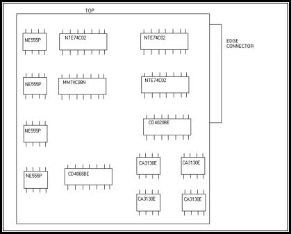
19. Detector Board (Instructions to Conversion Kit for New Detector Board)
Detection of flaws by the NDT is accomplished by sensing a current change
If an arc occurs in the tire and the detector does not trigger a flawed condition there could be a number of possible reasons for this. However, the first step is to check the high voltage resistors, then the coax cable, current transformer, and its connectors. Read more….
Detector Board Outputs
(read more 1) Occasionally, due to atmospheric conditions, or variance in the input voltage of the NDT, the sensitivity of the Hawkinson Detector Board may need adjustment. (Old Board Adjustment, New Board Adjustment Read more….)
To adjust the sensitivity of older detector circuits
1. Set digital multimeter to DC volts
2. Connect the meter's DC negative to 12 Volts DC Negative (Use the black wire that is connected to the wiring harness of the new computer board.)
3. Connect the other meter lead to TP6
4. Adjust the potentiometer next to TP6. Turning the potentiometer counterclockwise increases the sensitivity. Turning the potentiometer clockwise decreases the sensitivity
To adjust the sensitivity of the new detector board follow these steps:
1. Set digital multimeter to DC volts
2. Connect the meter's DC negative to 12 Volts DC Negative (Use the black wire that is connected to the wiring harness of the new computer board.)
3. Connect the meter's DC positive to the left side of R13. R13 is a resistor located between R9 and R14. The left side of R13 is the side facing R9.
4. The factory setting should be 1.654 volts DC.
5. If the customer complains of missing flaws the sensitivity setting can be changed by adjusting the potentiometer R10 located directly above R13. Adjusting R10, by turning the screw counterclockwise will increase the sensitivity, and lower the DC volts displayed by the meter. Rotating the screw clockwise will decrease the sensitivity, and increase the the DC volts displayed by the meter. Settings of less than 1 VDC will typically be too sensitive, and trigger a flaw condition even if there is no flaw. Settings greater than 2 VDC will typically not be sensitive enough, and the detector will not trigger a flaw.
New Detector Circuit Adjustment Resistor and Potentiometer
(read more 2) In some cases the old detector circuit fails because one or more of the chips on the board fails. Replacement of the chips is an alternative to replacing the entire detector circuit board. However, most chips are difficult to source because the original equipment manufacturer no longer produces the chips.
IC Chips on Old Detector Circuit 1
Steps to complete the additional wiring to make manual operation compatible with the NDT circuit board (Applicable to machines with serial number less than PEH 0500).
Locate the two-amp breaker. For the INSP find the 2A fuse #6
Determine which side is the outgoing power side.
- Attach a new sixteen-gauge wire (wire number 1) to the outgoing power side of the two-amp breaker.
- Locate the Inside Up/down set of contacts and install a new normally open contact ZB2-BE101 to the top of the set of contacts.
- Terminate wire number one, to one side of the new normally open contact; on the other side of the contact attach another new sixteen-gauge wire (wire number two).
- Locate the high voltage on/off switch and contacts and attach a normally closed contact ZB2-BE102 to the top of the existing contacts.
- Terminate wire number two, to one side of this normally closed contact; on the other side of the contact, attach a new sixteen-gauge wire (wire number three).
- Locate the Manual button and set of contacts, and install a new normally open contact ZB2-BE101 to the top of the already existing set of contacts.
- Terminate wire number three, to one side of the new normally open contact; on the other side of the contact attach a new sixteen-gauge wire (wire number four).
- Locate the 12-volt DC relay (Wire B N.O.); remove the normally open push-on connector and terminate wire number four to the normally open knife of the relay, using the double push-on connector. Reconnect the old wire with wire number four using the double push-on connector on to the relay.
- Install the new circuit board using the 22-pin slide on connector or hard wire.
Note: Leave all existing wiring; it is not necessary to remove any of the old contacts or wires.
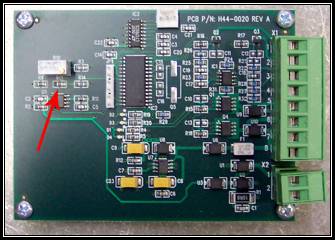
20. Motor Control Board
 Motor Control Board Overview
21. 12 Volt Power Supply
The 12-volt DC power supply is responsible for supplying power for the 12-volt DC relays, detector circuit board, flaw light, timer over light (test over light), start button, and safety contacts. The 12-volt DC power supply is protected by the 1-amp breaker. To check the 12-volt DC power supply check that the line voltage to the power supply is 120 VAC at the 1-amp breaker. Next, check the DC output is 12 volts.
A quick way to check if the power supply is working can be accomplished by pressing the flaw light lens, or the timer complete light (test over) lens . When either of these lenses are pressed the light should illuminate. If the light illuminates the 12-volts DC power supply should be considered good.
The 12-volt DC power supply is either din rail mounted or mounted in an aluminum frame.
27. Arm Swing In/Out
The normally open contact is used to supply 120 VAC to the arm swing in/out solenoid and to the Inside UP/Down switch. If the probe does not swing into the tire, the normally open contact may not be allowing electricity to pass. Ensure that the selector is set to the in position, electricity should be on both sides of the normally open contact. If electricity is not on both sides of the contact than replace the contact. Note, the probe will not go up or down if, the arm swing contact is not working.
Additionally, if the probe will not swing in or is mushy check the slow start.
32. Flaw Light – Diagnosing a Faulty Detector Circuit
The Flaw Light is designed to alert the operator of a flaw condition in a tire casing. Additionally, the flaw light can be useful in diagnosing issues with the NDT. The following checks can be made to diagnose a faulty detector circuit board using the flaw light. Any deviation from the following conditions signifies a defective detector circuit:
The flaw light should be illuminated when the probe is up and out of the tire.
- When the probe is initially swung in and down the flaw light should remain on until the start button is pressed.
- When the start button is pressed the flaw light will turn off, the motor should begin turning, and the high voltage should turn on.
- When the detector circuit finds a flaw the flaw light will illuminate.
- When the probe is lifted to the up and out position, the flaw light will illuminate.
To ensure that the 50 K potentiometer is not defective a meter capable of detecting resistance is necessary. Disconnect the white wire that routes from the motor control board to the potentiometer. It is best to disconnect the wire at the motor control board, rather than de-soldering it from the potentiometer. Set a meter to check resistance. With one lead from the meter attached to the disconnected white wire, and attach the other meter lead to the black wire where it soldered to the potentiometer. Next, watch the display on the meter while tuning the knob of the potentiometer. If an open is displayed than the potentiometer is defective, and is the reason the motor does not work. If the potentiometer displays varying resistances ranging from 0 ohms to 50 k ohms, the potentiometer is not defective.
34. Test Over or Timer Over Light
This light uses a 12-volt DC bulb, and will illuminate when the detector board's timer runs out. This light does not signify that a tire being inspected has received a complete inspection. The light is signifies that the timer has completed counting down or up, depending on the type of detector circuit installed. The Test Over / Timer over Light is installed for safety reasons. For example, if the start button was pressed and the operator leaves his station, the machine would automatically stop after 30 seconds or less.
35. 12 Volt DC Relay
There are two identical 12 VDC relays in the NDT. Both relays use a 12 VDC solenoid, powered by the 12 VDC power supply. There is always 12 VDC positive going to the solenoid. However, the only time 12 VDC negative will be available for the solenoid is when the detector circuit feeds the 12 VDC negative to the relay. The detector circuit will only send the 12VDC negative voltage to the solenoid if the probe is in a tire to be inspected.
36. 1-Amp Circuit Breaker
The 1-Amp circuit breaker protects the 12 VDC power supply. The 1-amp circuit breaker feeds 120 VAC to the primary of the 12VDC power supply.
37. 2-Amp Circuit Breaker
The 2-amp circuit breaker protects the 50 KV power supply. If there is no high voltage the first place to check is the 2-amp circuit breaker to ensure it has not been disengaged. If the circuit breaker is disengaged that signifies that there is something wrong with the high-voltage circuit. Usually, this means that that one of the following has failed: 1) the 50 KV power supply, 2) the 1 Meg or 20 Meg resistor, or 3) either of the capacitors. Do not continue to operate the NDT if the 2-amp circuit breaker disengages without examining the cause.
42. Air Solenoid Probe In/Out
Electricity from the arm swing in/out contact supplies this solenoid with power. If power is reaching the solenoid when the arm swing contact is in the "In" position check if air is passing through the valve that the solenoid is connected.
44. Air Valve for Probe In/Out or Up/Down - Air Kit 1 Instructions, Air Kit 2 Instructions, and Air Kit 3 Assy Instructions.
On the In/Out valve, air is routed through the middle port on the side of the valve that has three ports. The other side of the valve has two ports and one port is for air to push the probe into the tire, the other port is for air to push the probe out of the tire.
45. Air Regulators for ProbeAir Kit 1 Instructions, Air Kit 2 Instructions, and Air Kit 3 Assy Instructions.
48. Slow Start
If the slow start is not working properly, the swing arm/probe may not swing in, out, up, or down very effectively. Follow the instructions to adjust the slow start.
52. 31-10 BnC
The 31-10 BnC Connector is part of the Current Transformer. The wires that connect to this connector are polarity sensitive.
On older NDT machines where the Current Transformer is mounted to the Mast Swing Arm, there are two yellow wires soldered to the 31-10 BnC Connector. One of the wires is colored black with a permanent marker. It is critical that this wire be soldered to the outside pin of the BnC connector. If the wires are soldered to terminals on the BnC connector so that the polarity is backwards, or if solder shorts the terminals of the BnC the Specific Frequency will not be sent to the detector board and flaws will be missed.
53. Reverse Relay Assy
Reverse Relay Assembly
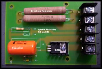
Breaking Resistor
Motor Control Board with Alternative Breaking Resistor
If the motor stops working it could be a number of reasons. However, check the brushes of the motor. There are two brushes that could cause the motor to stop working. The motor is a 90 VDC motor. If 90 VDC or less is applied directly to the motor, the motor should turn if it is not defective.
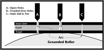
Depending on the construction of the tire (steel or bias) the NDT can detect the following:
Steel Belted
- Through holes that are between the probe chain bar and the ground roller (A)
- Partial holes inside the tire that extend to the steel belts (B)
- Partial holes between the steel belts of the tire and the ground roller (C)
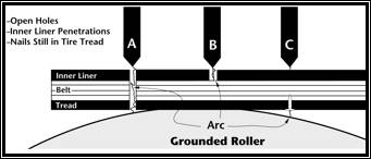
Bias Ply
- Through holes that are between the probe chain bar and the ground roller (A).
- Embedded objects that touch either the chain bar or the ground roller (B and C).
Questions on Repetition (no electrical arcing)
I have an NDT that did not arc to an obvious flaw why not?
Hawkinson—If potential exists for electricity to arc to a flaw the NDT will arc every time. If the NDT did not arc than no potential existed. After checking the NDT for mechanical failure the next step is to analyze other reasons why an NDT will not arc to a flaw:
- When a tire is spread on the NDT, the degree of spread can vary. When a tire is spread, flaws can open, or flaws can close. If a flaw closes tightly it is possible that potential to arc does not exist, therefore, no arc will occur.
- A conductive object is imbedded within the tire and surrounded by nonconductive properties. There is no potential for an arc of electricity to occur therefore no arc. (This problem can be reduced by adding an NDT after the buffer or as a final inspection unit. Occasionally, an imbedded piece of metal will be missed by the NDT and will be forced out of position by the buffer or a pressure chamber. Materials, labor, and adjustments can be reduced by adding NDTs to inspect tires after buff and during final inspection.
- If the probe or ground roller does not touch the flaw, no potential can exist. (This problem is typical. Sidewall wires on the probe become deformed and do not touch parts of the tire. Replacing sidewall wires regularly can reduce missed flaws.)
- The rotation speed of the tire causes a flaw to pass under the probe when no electricity was available to arc--The NDT makes a distinct ticking sound as high voltage is applied. When a ticking sound is heard, electricity is applied to the tire. Between ticks, no electricity is applied to the tire. The slower the NDT rotates the likelihood of an arc to occur is greater. The average time to "electrically" inspect a tire is less than 32 seconds. However, most retreaders who use the NDT also use it to conduct a visual inspection and some use the NDT to make repairs to the tire at the same time as inspection. Install a manager's speed kit to ensure your operator does not electrically inspect tires too fast - Motor Speed Kit 1, Motor Speed Kit 2.
Questions on Repetition (automatic mode arcing observed)
The NDT arced but did not stop automatically while in the start (automatic) mode. How to Detect a defective detector circuit board.
Hawkinson—From time to time this phenomenon will happen, hence the importance to remember the NDT is a tool and requires a well-trained operator to maximize the NDT guarantee. Here are some facts the operator of the NDT should be aware of:
- The NDT makes a distinct sound when an arc occurs. Therefore, if an arc is heard or seen, but the NDT does not automatically stop, the operator must manually stop the tire rotation and use the manual mode of the NDT to locate and investigate the flaw.
- When two or more flaws are located within close proximity of each other, the detector of the NDT may not be quick enough to stop for the first hole but may stop for the last.
- The NDT arced to a large obvious flaw but did not stop. This can occur because the NDT was designed to find flaws that are small and not visible to the eye. An arc to a small flaw causes the currant flow to rise and fall quickly. This quick change in currant is how the detector determines a flaw exists. Therefore, a rapid rise in current that remains high [large hole] and does not fall quickly will not trigger the detector.
Questions on Reliability
Hawkinson—Test tires are NOT an effective way to determine the NDT's reliability. Typically, test tires are created by drilling or puncturing holes in a tire. Drilling or puncturing a hole in a tire will cause a very clean hole. Whereas, a tire that is punctured by a nail on the road will collect contaminates, which may contain conductive material and will push the nail in and out of the tire many times. The best way to test the reliability of the NDT should be accomplished by conducting the spark test. The spark test is explained in the owner's manual. The NDT guarantees that the NDT will reduce the adjustment rate compared to visual inspection alone.
How can the NDT save money?
Customer—Can the NDT save me money?
Hawkinson—Compare the cost of the NDT to the cost of adjustments. Tests conducted by an independent consultation service proved that the NDT will find flaws in tires that are missed during visual inspection. In fact, the independent testing services concluded that the NDT would find significantly more flaws in tires compared to visual inspection. Compare the NDT to other types of inspection equipment such as shearography, x-ray, or ultrasound and the NDT will be the most affordable, efficient, and reliable machine. The upfront cost of the NDT is less than many of the other inspection methods and long-term maintenance is typically minimal. Labor costs are less than many other inspection methods. Production costs can be reduced; reducing the number of times buffer blades must be replaced from missed objects in the tire; the amount of material waste due to undetected flaws is reduced. The NDT is durable and dependable and has been the standard in North America for the last 20 years. My machine is missing flaws, what is wrong?
The following describes a sequential and logical order of trouble shooting the NDT and is common for all model NDT machines.
First, check the high-voltage cabinet to ensure that the critical frequency is good. Measure the 1 Meg, 20 Meg, 75 Ohm, 5 K Ohm, and 150 Ohm resistors (How to measure the resistors), measure the High-Voltage Coil, clean and cycle the High-Voltage Relays, gap the Capacitors (How to gap the capacitors).
Wipe down the cabinet and vacuum out all of the dust and debris. If there is corrosion, install an NDT-Kit, Hawkinson Part Number H05-0008. Install an NDT-Kit once every five years or as needed.
Check the 2-amp breaker to ensure that the breaker did not disengage. If the breaker is disengaged, click on the Hyperlink for the 2-amp breaker.
Check that the coax cable, current transformer, and detector board cables are all connected, and there is no obvious damage. If damage is noted, or questionable, click on the Hyperlink for a specific component for specific directions.
Check that the probe is in alignment.
Try a spark test (spark test directions).
High-Voltage Cabinet Overview
There are many companies that use the Hawkinson NDT to ensure that their retreaded tires are of the highest quality. For example:
Michelin
Please take a look at this link and download the Nail Hole Inspection video.
Wingfoot / Goodyear
The link shows a picture of the NDT-II made by Hawkinson, which is used by Goodyear.
Bridgestone / Bandag
The link below shows the NDT-IIB being used by in Bandag's retread process at approximately the 2:00 minute mark.
What maintenance should I do to the NDT?
NDT® User Maintenance (User Maintenance Schedule)
Probes should be vertical, centered in the tire, and properly placed over the metal drive roller.
Air should be set to specs as per operator's manual. Never adjust air pressure to compensate for dirty, sticking V-bearings.
Worn and broken items such as sidewall wires, plastic paddles, roller bearings, spread rollers, and key chains hinder performance of the NDT®. It is not necessary to over-tighten the screws that hold the sidewall wires in place.
Inspect the NDT® for broken, worn, or wearing parts. Do not wait for a worn part to fail before replacement.
Pay close attention to:
- high voltage wires
- black coaxial cable
- loose screws
- tie-wraps
- ground straps
- resistors
- switch activators and contacts
Basically, there are two functions of the NDT® that allow it to find flaws in tire casing:
- Voltage is applied to the casing that creates an electrical arc when a flaw is present.
- The detector circuitry senses electrical current changes when an arc occurs.
The gap between the carbon balls in the high-voltage cabinet is the only adjustment the user has control over that can affect the current applied to a tire casing. The gap should be 11/16 inch. Speak to a technician before attempting to measure or adjusting the gap.
Sensitivity is adjusted by a potentiometer located on the detector circuit board. Hawkinson presets this at 4 volts on older detector circuit boards, and 1.654 on new detector circuit boards.
A clean machine works better and looks better. Follow these suggestions for proper NDT maintenance:
Engine de-greaser works well for cleaning the drive roller, v-rails, and other parts where heavy gunk collects.
This is a common problem with the NDT and is usually a simple problem to fix. Typically, the problem occurs because there is a small pinhole in the probe wire, or the high-voltage output wire. Replacing these two wires nearly always fixes the problem.
If the problem continues to persist after replacing the probe wire and high-voltage output wire, the machine may have a defective detector circuit board. To check the detector board, disengage the 2-amp breaker in the operator's console. Next, place a tire on the machine, and begin the electronic inspection. When the Start Button is pressed, the yellow flaw light turns off and the motor should turn. There will be no high-voltage. However, the motor should turn, and the green timer over light (Test Complete) should illuminate after approximately 30 seconds. If this is, the case detector board is not the problem.
However, if the motor does not turn check the 12-volt DC power supply, and 12-volt DC relays, and cables between the detector circuit board and operators console. If they are good, replace the detector circuit board.
If all else fails replace the coax cable, and if the problem persists, the only other component that can cause this situation is the current transformer, so replace that as well.
My motor won't turn, why?
Six systems can cause the motor to stop turning. Five of the six can be analyzed, and by process of elimination, the sixth can be diagnosed.
First, check the 12-volt relays, and 12-volt power supply. Next, check the 50 K potentiometer. Next, check the direction switches on the operator's console, then on the front remote location. Next, check the motor contactors (not all NDT machines have motor contactors). Finally, check the motor. If all of the aforementioned parts are good, replace the motor control board.
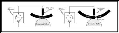
Critical Frequency
Imagine the high voltage cabinet as a radio. The radio transmits a specific frequency, which is created by the high-voltage power supply, resistors, and gapping of the capacitors. The specific frequency travels up the antenna, which is the high-voltage output wire to the tire. A receiver, which is the current transformer, intercepts the specific frequency and sends the signal through the coax cable to the detector circuit. The detector circuit listens for changes to the specific frequency. When an arc occurs, the detector circuit realizes a change has occurred, which then triggers a flaw condition. If an arc occurs anywhere along the antenna, the detector will trigger a flaw condition. The arc does not have to occur in the tire.